The Foxcroft Blog

2 min read

The Foxcroft.com Blog: How it works (part 2)

By Michael Brooks on Wed, Aug 29, 2018 @ 11:35 AM

 FX-1000p amperometric chlorine analyzer     Welcome back to Foxcroft.com Blog, this is the second part of the blog that was posted on 5/20/11.

      The cell electrodes are connected to the amplifier section of the electronics, where the low level amperage is boosted and ranged to a usable signal. Specifically, 0 to 5 volts DC. The 0 to 5 VDC is then input to and isolation amplifier, which provides electrical isolation and an electrical safety barrier. The 0 to 5 VDC output of the isolation amplifier is then doubled to 0 to 10 VDC, which is used in the final 3 output stages of the circuit. These are the LED display, the alarm circuit and the 4-20 milliamp DC output signal. The amplifier board is powered by a dual bi-polar regulated DC power supply, which provides two sets of +12 and -12 volts. The LED display provides an instantaneous numerical reading of the chlorine residual in parts per million.The alarm circuit provides two user adjustable alarm level settings that activate two relay outputs, which can be used to control external devices or alarm annunciators. The FX-1000p amperometeric chlorine analyzer has been design with process control applications in mind, and as such, is an excellent choice for use in process control of chlorine residuals in freshwater, wastewater, salt water and food processing.

      Amplifier board calibration is done at the factory, with a default range of: 0 to 5 ppm. The unit can easily be re-ranged in the field. The analyzer can be ranged anywhere from a low of 0 to 0.5 ppm to a high of 0 to 60 ppm. On-site standardization (chlorine residual calibration) is done when the unit is commissioned, and thereafter needed or desired, using an accurate chlorine residual titrator (or test kit), and chlorinated and non-chlorinated sample of the process waters being analyzed.

     If you would like more information or a quote please click on the following link:

describe the image

Continue Reading
1 min read

The Foxcroft.com Blog: How our analyzer works (part 1)

By Michael Brooks on Wed, Aug 29, 2018 @ 10:32 AM

FX-1000p Amperometric Chlorine Analyzer     Foxcroft Equipment & Service Company's Amperometric Chlorine Analyzer's residual reading is determined by measuring the amperage produced by oxidized chlorine in the measuring cell. The amperage level is directly proportional to the level of free chlorine available in the sample stream. When reading total chlorine, the unit is actually reading converted free iodine from potassium iodine that is added to the cell for Total Chlorine readings.

     The cell itself is constructed such that the sample that runs through it does so at a continuous and fixed rate. Any additional flow is allowed to overflow to waste from a drain below the overflow weir. The sample stream runs down though the lower block, where it mixes with vinegar (and Potassium iodide where Total Chlorine is being analyzed), and then flows upward into the measuring cell. Within the cell, the vinegar provides pH buffering to a value of 4.0, and aids in keeping the cell clean. If Potassium Iodide is being used to read Total Chlorine, it chemically converts any free and combined chlorine residuals into free iodine, which is then read as a total chlorine reading. The cell utilizes a mixer and 150 pvc balls to ensure even chemical mix, clean the electrode and consistent readings. Very pure grades of gold and copper are used in the construction of the electrodes to enhance signal strength. Sample flow leaves the cell from the top and runs out a secondary drain to waste.

See part II to follow

Written by: Gavin McCulloch

Continue Reading
4 min read

Tech Tip: What is the VDC on the Calibration Screen?

By Ray Sullivan on Mon, Oct 23, 2017 @ 04:28 PM

While calibrating your FX-CLv2 chlorine analyzer you've seen values for "VDC" along with the PPM residual readings. What is VDC and why is it shown?

In an amperometric chlorine analyzer a voltage is applied to the measuring cell. When chlorine, or any other oxidizing substance, contacts the positive measuring electrode it oxidizes and produces a current. This current is proportional to the concentration of chlorine in the water sample.

The VDC, or volts DC, is a measure of this current generated by oxidation in the sample from which the residual measurement in parts per million (PPM) is produced. The total possible voltage range of the system is 5 volts.

What are the numbers on the calibration screen?

The calibration screen below shows three sets of numbers:

Voltage produced at calibration values.jpg

Top left "Chlorine Zero": Zero Point value in PPM entered at the last calibration, and the VDC measured when it was last set.

Top right "Chlorine Standard": the last Standard (span or grab sample result) calibration value in PPM entered, and the VDC measured when it was last set.

Bottom Center "Residual": Live readings in PPM and the associated VDC which are producing the PPM result. Note that this measurement is determined by the slope set by the last calibration.

When calibrating you are defining two points within the analyzer's operating range, usually 0-5 PPM. The first point is zero, the second is the residual typically measured with a portable colorometric chlorine analyzer. These two points define a linear slope, every X amount of voltage is equal to Y PPM up to the limit of the operating range.

There should be near zero volts being produced when you set the zero point. However, many water sources produce a "background voltage" even when no chlorine is present, so you may never reach zero volts in your calibration.

Not to worry, when you notice the VDC stabilizes at it's lowest level and you enter 0.00 PPM, you shift the zero point up to that voltage level, effectively cancelling out the background voltage. Any measurement beyond that point will be produced by chlorine.

The Analyzer Will Do What You Tell It To Do Via Calibration

It's important to remember with digital measurements that the operating software, like a computer, will do what you tell it to do through your calibration values.

One customer's analyzer always produced 0 PPM: Chlorine Zero was set as 0.00 PPM as required. The Chlorine Standard was also entered as 0.00 PPM. When they returned to the Home run screen they and their SCADA saw the analyzer always measuring 0.00 PPM chlorine. They had defined the output to be zero, which is what they got.

Another calibrated a negative slope as shown below. Since the operating software assumes a positive slope, negative slopes can produce unpredictable, incorrect results.

Below, the live reading produced was seen when we were feeding de-chlorinated water to set the zero point. Note the very low 0.003 VDC produced by zero chlorine in the sample produced a large 3.15 PPM residual measurement.

Negative calibration slope.jpg

In the last calibration, the 1.457 VDC indicates there was chlorine in the sample when the zero point was set; this value should be 0.050 VDC or less when you enter "0.00". You'll note the 0.443VDC when 2.200 PPM was entered.

Why Is VDC Displayed?

The VDC is included as a calibration guide and trouble shooting tool. A wastewater customer's analyzer was measuring almost 5PPM of chlorine being discharged from the plant while grab sample and lab results showed negligible levels of chlorine. The state DEP investigated and found that an industrial customer was illegally dumping manganese into their waste stream. In this case the analyzer was able to detect a substance that the colorometric instruments could not.

Final Tips

  • Don't obsess over the VDC, but paying attention to it can show if a calibration was entered properly, or indicate a problem if grab sample results don't look right or match the analyzer readings.

  •  For the highest resolution and less erratic readings, there should be a significant difference in VDC between your zero and PPM entries when calibrating your analyzer. We recommend that your span, or standard calibration be performed at least half of the operating range limit. For example, on a 0-5ppm range analyzer your grab sample span calibration should be done with about a 2.5ppm solution.
  • As shown in the first photo above the difference between zero (0.001 VDC) and 1.439 PPM was 2.068 VDC. If the chlorine standard was set at X PPM at say 0.200VDC, the readings would be "jumpy" or erratic because a minute change in voltage will result in a large change in your PPM reading. Your reading will be correct, but you will see wide swings in residual on your  chart or SCADA plot.

  • Don't use deionized or distilled water to set the zero point. These will likely generate no current. When your process water is fed, any background voltage present that is not produced by chlorine will be interpreted as being chlorine, resulting in high readings. Always remove chlorine from your process water with a carbon filter, or take a sample before chlorine is injected for the most accurate zero point.

  • If you don't have a carbon filter installed, you should feed dechlorinated process water from a 5 gallon bucket with a small submersible pump. Don't simply pour water from a bottle. Remember that  amperometric chlorine analyzers  are flow sensitive and require a consistent flow rate.

  • When you enter the calibration screen from the home page, the analyzer maintains the last measured residual milliamp output until you are finished calibrating and return to the Home page. This is intended to prevent disruption to your chemical feed control.

  • Your calibration entry won't appear immediately upon returning to the Home screen, the analyzer will take several seconds to ramp up or down to your entry.


Go To The FX-CLv2 Web Page  

Continue Reading
3 min read

The Motor Stopped in My Chlorine Analyzer!

By Ray Sullivan on Thu, Sep 28, 2017 @ 02:47 PM

While starting up a new FX-CLv2 chlorine analyzer we sometimes get a call for help from a customer: "I need to return this analyzer. I calibrated, it was running fine, and then the motor stopped. My old FX-1000P didn't do this, what's wrong?"

First we explain the analyzer is working as designed - the No Flow sensor in the measuring cell didn't detect sufficient flow to the measuring cell, so it signaled the processor to turn off the mixing/stirring motor. The buffer feed motor is also turned off during no flow conditions so as not to waste the pH buffer.

no flow sensor FX-CLv2.jpg


It also displays a "No Flow X" alarm on the local touch screen display.

No flow alarm FX-CLv2 chlorine analyzer.jpg


It also energizes the no flow alarm relay, indicated by the LED, to alert you to the flow interruption via your SCADA or remote monitoring system:

no flow relay FX-CLv2 chlorine analyzer.jpg


After hearing this, the customer will usually say that their old analyzer didn't do this, and they'd like the old style instead. Why is this included anyway? Can we bypass this?

The customer is right, the "old" FX-1000P did not have a no flow sensor; when flow was lost, usually due to a bubble blockage, the motor kept running. The customer wouldn't realize there was a problem until......

Without a continuous supply of water the electrode eventually overheats. The measuring electrode expands due to thermal expansion, the gold tube portion of the electrode then cracks or distorts, causing a water leak between the gold tube and copper post on which it's mounted.

This "short circuit" would cause constant, wildly fluctuating residual readings, prompting a tech support call. After a few questions examination of the electrode would confirm it was destroyed and required replacement, costing over $1,000 dollars.

When we started the re-design of our FX-1000p chlorine analyzer to the digital FX-CLv2, we attempted to resolve or avoid as many issues as possible to make the new analyzer as trouble-free as possible.

We included the optical No Flow sensor in the measuring cell to prevent destruction of the measuring electrode. It works as stated above with an interruption in flow; when flow is restored it turns both motors on, resets the no flow alarm, and displays that flow is restored on the touch screen display with the blue water drop and "FLOW" message.

To the question of "can this sensor be bypassed?", the answer is yes, but you'll first need to sign a waiver to confirm that you want this safety device disabled and will be responsible for the cost of a positive measuring electrode replacement, even during the warranty period.

Their "old analyzer" on the same sample stream probably did experience similar blockages; except that without the sensor and alarm present they didn't know it until the residual dropped to near zero (due to the chlorine being consumed at the electrode and not being replaced) or the electrode was damaged.

So why are the blockages occurring for some customers, or only in certain locations? Usually the flow interruption is caused by a collection of air or gas bubbles that block water entry into the measuring cell. Bubbles can be caused by a pump cycling off and on, but this typically occurs when sampling groundwater with entrained gas or air bubbles. We don't usually see this issue with surface water or wet well monitoring. As the water rises from the well or aquifer, it de-pressurizes, any micro-bubbles present expand in size and collect in the port in the lower block that holds the measuring electrode.

The solution is to use the overflow bypass fitting provided with each new system, or to use the fitting in combination with our flow rotometer.


Go To The FX-CLv2 Web Page

Continue Reading
3 min read

Reagentless Chlorine Sensors Are Not Always Low Maintenance

By Ray Sullivan on Wed, Sep 13, 2017 @ 11:24 AM


Many think reagentless chlorine sensors are always the best tools for online monitoring and control of free or total chlorine residual.

3 electrode Free chlorine sensor 020crop.jpg
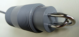
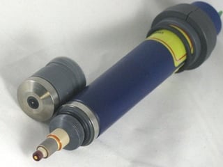
They have no moving parts and low consumables cost: just replace the electrolyte every 3-6 months and the membrane cap every year.

With no toxic reagents or buffer solutions, and low maintenance, chlorine sensors seem to be the perfect choice for any water system.


If your water does this to equipment, your "low maintenance" sensor will turn into a cost of ownership nightmare.

Iron in flow cell.jpg  iron in FX-CL-F 011.jpgCalcium in drains 045.jpg

Untreated groundwater with elevated iron, solids or calcium levels clogs the micro porous membrane, preventing chlorine from reaching the electrode. In addition to fouling the electrodes, too much iron will prevent 3-electrode sensors from producing an output.

The sensor shown above needed membrane cleaning and electrolyte replacement every 3 days due to excessive iron levels, resulting in:

  • Inability to use a new SCADA system to control chemical feed.
  • Increased chlorine usage and cost.
  • Higher direct labor maintenance cost, and less time to perform other tasks.
  • Higher consumables cost.


There's a proper tool to do every job. As you wouldn't use a pipe wrench to replace a spark plug, you don't use a reagentless membrane sensor to measure chlorine in dirty water.

We define dirty water as containing any of the following and thereby being unsuitable for membrane covered chlorine sensors:

  • Wastewater
  • Potable water with iron, calcium, manganese, turbidity or total dissolved solids above US EPA Drinking Water Standards
  • Hydrogen Sulfide
  • Corrosion Inhibitors

To avoid selling you something that doesn't work, Foxcroft reviews your application first and recommends the better of two types of instruments that best suit your process.  

Our bare electrode model FX-CLv2 excels in dirty or clean water; and our reagentless chlorine sensor models are for free or total chlorine in filtered, clean water.

Don't assume that the most heavily marketed product is always best for your application. We don't hesitate to recommend probe based systems, if there is a high probability it will work without undue attention and maintenance.


Contact us  for more info


Continue Reading
4 min read

Sensors: Make Sure They Suit Your Application

By Ray Sullivan on Tue, May 14, 2013 @ 11:14 AM

At times we see sensor specifications in plant upgrade or new treatment plant projects that don't appear to suit the particular application in the most cost effective manner.

Usually we see a pH sensor specified for potable water treatment with characteristics that far exceed the requirements of the process fluid. The sensor will work satisfactorily, but it costs much more than it should.

For one project a non-contacting torroidal conductivity sensor was specified for a non-corrosive surface water application with low conductivity, about 500uS.

There were several problems with this:

  1. As conductivity goes down, the uncertainty of the measurement for inductive type torroidal conductivity sensors goes up significantly.

  2. Inductive sensors are primarily a good choice for cases where there are very corrosive acids, bases or electrolytes that would otherwise quickly degrade the metal electrodes on a contacting conductivity sensor.

  3. Inductive sensors are an excellent choice to measure VERY high conductivity samples.

  4. Inductive sensors are a good choice to avoid fouling, bubble formation in the measuring cell, or the accumulation of debris.

None of these conditions applied to the application.

Providing more than is expected or paid for is a good thing for customers. Paying more for something that's not needed is not so good. Paying double for decreased accuracy and unneeded features, as in this case, just can't happen for municipalities with tight or shrinking budgets and for all of us who live in those municipalities.

For this project we proposed a contacting conductivity sensor with a cell constant and range appropriate for the application. The sensor design we offered, shown below, features a CPVC insulator for typical water treatment plant chemical resistance, 316 SS electrodes, double O-rings,and provides little if any potential for debris build up.

Foxcroft conductivity sensor resists fouling


Reducing sensor cost isn't achieved by reducing price or quality, it's achieved by selecting a sensor with appropriate characteristics. The benefit my be seen through better process control, less frequent cleaning, less frequent calibration, longer sensor life, or a lower purchase price.

For some applications, like fluoride resistant pH measurement, you may initially pay more than you would for a "competitive" sensor. But, you can actually lower your cost with our HF and acid resistant pH sensor by obtaining accurate measurements, replacing the sensor less frequently, and by surviving infrequent process upsets that wipe out most sensors when the pH drops dramatically.

Our sensor mentioned above does not contain antimony, extra thick or coated standard pH glass. Rather, it features a specially engineered pH glass, actually a glass like material, for fluoride resistance and a reference junction engineered to function in acid. It not only resists deposits on the glass surface, it can survive acid service and cleaning. Since this is now a "standard" sensor, you get a high performance sensor without a "custom engineered" price.

In many applications you may lower operating cost by simply matching sensor components to suit your process instead of using a "one size fits all" approach that may actually be over or under engineered for your particular type of water.

A customer monitoring wastewater for low pH influent with a lowest cost general purpose probe can dramatically increase sensor life with a sulfide resistant submersible pH sensor.

It's important to note that not all sensors are designed, or, "created" equal. Many of the sensors used in our instruments were designed specifically, and rigorously field tested, to overcome longstanding difficulties in process measurement while providing accuracy and repeatability. Some of these sensors have no design or functional equivalent anywhere in the market.

The take away from this is to check that the sensor being offered to you is actually suitable and optimal for your process. Among many questions you should consider:

  • Is it accurate in the range required?

  • Does the sensor body material's chemical compatibility, pressure and thermal resistance match the process fluid?

  • Can the sensor withstand the process fluid, and perhaps more importantly, the chemicals and physical force needed to clean it? Even though your wastewater may have a mid-range pH, your pH sensor may need to withstand acid cleaning of scale buildup. In some cases we recommend using a 15% HCL solution because 5% dilute HCL solution is insufficient.

  • Does the reference junction and or ion selective membrane have the design and chemistry suitable for the application?

  • Can a sensor with an external preamplifer provide equal performance than a more costly sensor with an integral preamplifier? With this approach you buy the preamplifier one time instead of with every replacement sensor.

Before making your next sensor purchase, don't automatically settle for what is offered, you may be able to get better process performance while helping your staff's workload and budget.

Contact us  for more info


Continue Reading
3 min read

Brain Eating Amoeba & DPB's: Pass Me The Chlorine Please

By Ray Sullivan on Fri, Oct 19, 2012 @ 11:21 AM

What's in your waterA recently published article reported the Center for Disease Control found that two adults from different households in Louisiana died from primary amebic meningoencephalitis (PAM) after using their household tap water in neti pots to irrigate and clean their sinuses.

PAM is an infection with a fatality rate of over 99% caused by the amoeba Naegleria fowleri (N. fowleri), often referred to as brain eating amoeba. The median time from the onset of symptoms to death is 5 days.

According to the CDC report the organism has been found in freshwater lakes, ponds, rivers, hot springs, thermally polluted water, warm groundwater, inadequately treated swimming pools, sewage and soil. Although extremely rare, PAM is typically contracted when water containing N. fowleri enters the nose while swimming in warm freshwater lakes and rivers.

Although most cases have occurred in the south, the range of cases has expanded northward with cases reported in Minnesota, Kansas, and Virginia.

The CDC report on the Louisiana cases stated that the municipal water was treated with monochloramine, and that cultures developed from samples from the distribution system and point of entry of municipal water into the two residences returned negative results for N. fowleri.  The organism was found in tap water and neti pot samples in both homes.

While reading this I thought of all the outcry to eliminate the use of chlorine in drinking water; and the communities that are fighting proposals to safeguard public health by chlorinating their water.

Waterborne diseases such as cholera, typhoid, and dysentery have been virtually eliminated where water is treated with chlorine. The World Health Organization estimated in 2008 that over 4,000 people die each day from diarrhoeal diseases caused by contaminated water and lack of sanitation. Most of them are children under the age of 5 in developing countries.

The proven benefits of chlorination far outweigh any perceived benefits that can possibly be gained by avoiding, reducing or eliminating the use of free chlorine to disinfect drinking water. It's mind boggling that anyone would prefer to expose their families to the possibility of contracting a waterborne disease common in some developing countries or a rare infection such as PAM that can kill within 5 days.

Chlorine also provides residual protection from microorganisms beyond the point of treatment, in your home plumbing for example, something that ultraviolet and ozone treatment cannot. 

The samples taken from the kitchen and bathroom faucets of one of the Louisiana cases, (the other wasn't tested), were found to contain a total chlorine residual that ranged from 0.0 to 0.02 mg/l . The expected residual in the distribution system is 0.2 to 4 mg/l.

These cases highlight the importance of the annual temporary switchover to free chlorine disinfection employed by many water systems.

Although free chlorine is a more effective disinfectant against more pathogens than monochloramine, concern over possible long term health effects from disinfection byproducts (DPB's) that form in the reaction of chlorine with organic materials is beginning to limit its use.

I still haven't seen a report that definitively proves that DPB's cause cancer or reproductive problems in humans. If somone has, please forward me a copy. As a country we've been chlorinating drinking water for over 100 years. During that time mortality rates have fallen, the population has boomed, even after factoring out immigration. If properly chlorinated drinking water was that dangerous wouldn't we have known that by now?

When it comes to public safety it's good to be cautious. But wholesale changes in drinking water disinfection shouldn't be made until we know the changes will be more effective than our current proven course of action.

On balance, suspected possible long term health problems don't outweigh the known harm of immediately life threatening pathogens that can occur in untreated or ineffecively treated water. I couldn't live with myself if my 4 and 6 year old grandsons died from PAM because they were just goofing around while taking a bath in "pure and natural" water, or water that potentially, might possibly, be found to cause problems in the future.

Would I like pure and natural water in my house? No thanks, pass me the chlorine, and make it free please.

Continue Reading
2 min read

How Often Should I Calibrate The FX-CL Chlorine Analyzer?

By Ray Sullivan on Thu, Aug 09, 2012 @ 11:04 AM

This is a commonly asked question, as is “when do I need to recalibrate my analyzer?”

 The FX-CL series amperometric chlorine residual analyzer is designed to operate continuously, 24 hours a day, 365 days a year. The system requires little routine maintenance other than changing the vinegar buffering agent bottle as it becomes depleted and occasional calibration checks.  

 When to calibrate FX-1000P chlorine analyzer
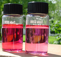
As part of a standard quality control procedure, we recommend the analyzer readings be verified using an accurate chlorine residual test instrument once every 7 days. In many applications, using a portable DPD colorimetric residual analyzer for routine calibration checks is sufficient to meet reporting requirements. For the utmost precision or in critical applications we recommend comparison with an amperometric titrator.

Calibration is typically done on an as needed basis, or at the minimum frequency specified by regulatory requirements. Barring any changes to the process or analyzer, the analyzer should be calibrated at least once per year.

You Need to Calibrate When:

If any of the following situations occur you should first verify residual measurements, make any required corrective measures, and recalibrate the analyzer.

  • If readings are not within ± 0.1 mg/L or ± 15% of a routine grab sample measurement.

  • If there is a change in sample flow rate to the analyzer.

  • If readings gradually drift up or down and there have been no apparent changes to the process.

  • If readings suddenly or unexpectedly change by a large amount. (NOTE: if the residual drops dramatically or to zero, first make sure you have sample flowing into the measuring cell, as evidenced by a discharge from the left drain under the measuring cell).

  • If the analyzer has been off line long enough to discolor or oxidize the copper negative cell.

  • If there is a change in the sample or if the analyzer is sampling a different source.

  • If the measuring range is changed.

  • After performing maintenance.

Calibration Guidelines:

You cannot simply enter calibration values with the analyzer running dry, with values that you expect to see, or with values from previous calibrations.

Calibration is always performed using water from your process.

Always set the zero point first.

When calibrating the zero point you must use dechlorinated process water, not distilled or deionized water.

Allow the measuring cell time to stabilize after switching water sources during calibration.

The standard, or span calibration value should be determined at about half of the analyzer's operating range.

Allow the measuring cell to stabilize to the process for 2-24 hours upon initial startup, after returning an offline analyzer to service, or after replacing the negative cell.

Continue Reading
2 min read

Foxcroft Back to Ecuador: Step 1 Toward Reducing Water Losses

By Ray Sullivan on Mon, Feb 06, 2012 @ 08:56 AM

As mentioned in a previous post, Foxcroft assisted in providing a water meter test bench to the City of Ambato, Ecuador last September.

In January of 2012 we and representatives of the MARS Company, the test bench manufacturer, were pleased to visit and provide start up assistance for the system delivered just after Christmas.

The process started when officials with EP-EMAPA, the Municipal Drinking Water and Wastewater Company of Ambato, estimated the city was losing about $1 million dollars per year in drinking water revenue between meter tampering and inaccurate water meters.

Management decided the first step was to address the most widespread issue, questionable meter accuracy. Rather than continue past practices, he believed the city would be best served by conducting its own meter testing and upgrading to the latest technology built to meet AWWA recommendations and NIST Handbook 44 specifications.

Electro-Mechanical Systems Engineer Max Pico chose the MARS Model 5-1000, an automatic double row bench that can test up to (10) meters 5/8" through 1" in one row, and up to (5) 1-1/2" through 2" meters in the second row with 1/10 of 1% repeatable accuracy using the gravimetric method. The system included a 500 gallon stainless steel tank and a 10 gal / 100 gallon duplex stainless steel tank. The system was provided and installed by our partner Amimechanical S.A of Quito, Ecuador.Mars test bench coontrol panel

Engineer Max Pico, left, at the MARS Co. computer control panel with a plant operator.

The test bench, which is compliant with ISO 4064 specifications, will help the city recover revenue lost to inaccurate water meters. In addition to testing the performance of their existing and newly purchased water meters, the bench will also provide valuable data to help evaluate future meter purchases.

Mars model 5-1000

Mars Co. president Floyd Salser with the MARS Model 5-1000 test bench in Ambato Ecuador

Since these test systems often pay for themselves in less than one year, we're looking forward to updates on how the test bench is contributing to their meter management program.

Continue Reading
1 min read

How to Save Chlorine Gas Money and Protect Your Operators

By Ray Sullivan on Mon, Jan 30, 2012 @ 11:38 AM

I wanted to share a good idea that can help save money on chlorine gas while protecting your personnel.

Brian Gunn, of Coastal Chlorinators in Savannah, GA has a customer who prefers dual channel chlorine gas detectors in his remote well sites instead of the typical single sensor gas detector.

The customer places one sensor inside the well house to protect personnel, and the other sensor outside at the vent, so it will alarm if the chlorinator malfunctions. With the detector's alarm relay connected to a phone dialer, officials can be notified immediately instead of being surprised during an onsite visit after a month of wasting gas.


Dual channel gas detector for well sites

Of course, the environment is also protected from a prolonged chlorine gas leak.

If you have any other "cool tricks" please feel free to share them. When it comes to water and the environment, a good idea can benefit everyone.

Continue Reading

Featured