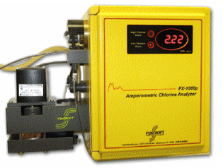
 Welcome back to Foxcroft.com Blog, this is the second part of the blog that was posted on 5/20/11.
Amplifier board calibration is done at the factory, with a default range of: 0 to 5 ppm. The unit can easily be re-ranged in the field. The analyzer can be ranged anywhere from a low of 0 to 0.5 ppm to a high of 0 to 60 ppm. On-site standardization (chlorine residual calibration) is done when the unit is commissioned, and thereafter needed or desired, using an accurate chlorine residual titrator (or test kit), and chlorinated and non-chlorinated sample of the process waters being analyzed.
If you would like more information or a quote please click on the following link:


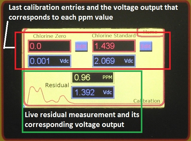
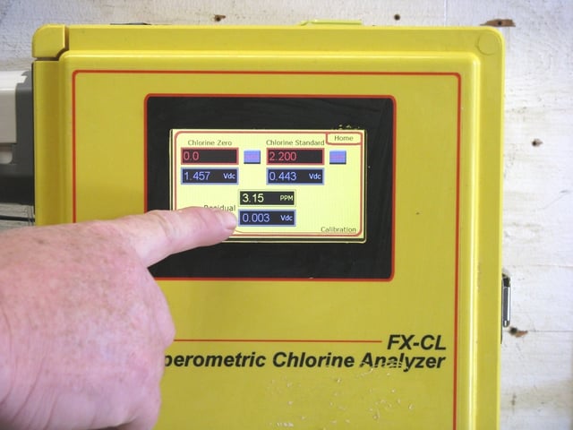

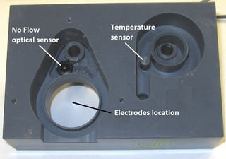
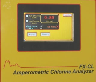
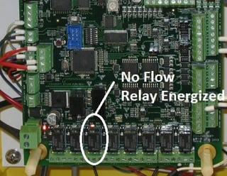
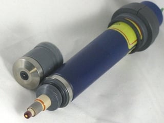 They have no moving parts and low consumables cost: just replace the electrolyte every 3-6 months and the membrane cap every year.


 A recently published article reported the Center for Disease Control found that two adults from different households in Louisiana died from primary amebic meningoencephalitis (PAM) after using their household tap water in neti pots to irrigate and clean their sinuses.
 As part of a standard quality control procedure, we recommend the analyzer readings be verified using an accurate chlorine residual test instrument once every 7 days. In many applications, using a portable DPD colorimetric residual analyzer for routine calibration checks is sufficient to meet reporting requirements. For the utmost precision or in critical applications we recommend comparison with an amperometric titrator.
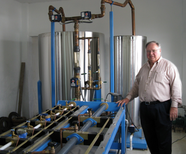


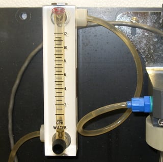
 In an effort to conserve water more of our customers are asking about reducing the sample flow rate into their amperometric chlorine residual analyzers.
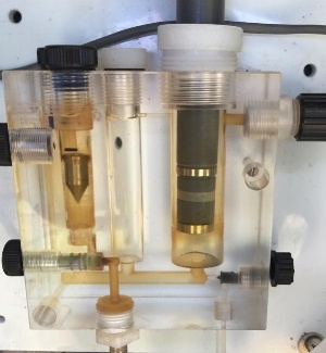
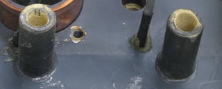
 Occasionally we encounter flow reduction or blockage in chlorine analyzers monitoring certain groundwater sources.
 So why does our model
  "If there's a hole in a sodium hypochlorite truck, the liquid spills on the ground and there's no big toxic cloud. It's what they call an inherently safe technology."